Views: 0 Author: Site Editor Publish Time: 2026-07-20 Origin: Site


Precision sheet metal bending scales fabrication throughput, maintains tight tolerances, and reduces scrap rates on the shop floor. Outdated forming equipment creates severe operational bottlenecks. You face inconsistent bend angles, slow setup times, and an over-reliance on scarce, highly skilled operators. This guide provides a comprehensive decision-making framework for evaluating, sizing, and investing in the right bending technology for your specific production environment. A Press Brake Machine is the primary engine of modern fabrication. Selecting the right equipment dictates your shop's efficiency. You must match machine capabilities to your exact material requirements. Over-sizing wastes energy and floor space, while under-sizing leads to machine damage and rejected parts. We will explore core mechanics, drive systems, and tooling strategies. You will discover how upstream design decisions impact downstream forming success, empowering you to optimize your production floor.

Technology Alignment: Selecting between hydraulic, electric, and hybrid press brake machines depends strictly on your shop's required tonnage, cycle speed, and energy efficiency goals.
Precision and Control: Modern CNC press brakes with multi-axis backgauges and automatic crowning drastically reduce setup times and operator error compared to manual or NC systems.
Tooling Dictates Capability: The machine is only as capable as its punch and die setup; understanding air bending vs. bottoming is critical for tooling investments.
Design-for-Manufacturability (DFM): Successful press brake forming relies heavily on upstream design decisions, including bend radius, K-factor, and material grain orientation.
Table of Contents
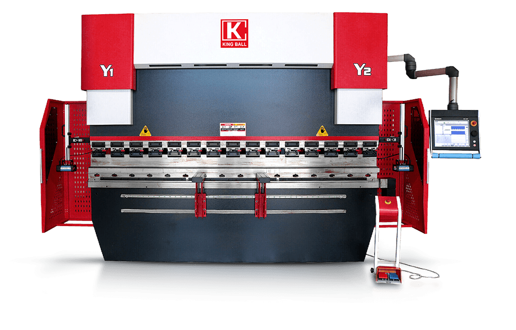
A Press Brake Machine operates on a straightforward mechanical principle. It presses sheet metal between two specialized tools. The top tool is the punch. The bottom tool is the die. These tools align along a vertical bending axis. The machine forces the punch down into the metal. The metal then conforms to the shape of the die below. Understanding this interaction is fundamental to mastering sheet metal fabrication.
The punch attaches to the upper beam, called the ram. The die secures to the lower bed. The ram moves downward along the vertical axis. It applies immense pressure to the workpiece. The geometry of the punch and die determines the final bend angle. Different profiles accommodate various shapes and clearances. Proper alignment between the upper and lower tools is non-negotiable. Misalignment causes uneven bends and accelerates tooling wear. Operators must indicate the tools during setup to ensure perfect parallelism across the entire bed length.
Tonnage represents the total bending force the machine can exert. It distributes across the entire bending length. Tonnage is the primary success criterion for machine selection. If you lack sufficient tonnage, you cannot bend the metal. If you apply too much tonnage, you risk fracturing the material. You also risk permanently damaging the machine bed. Required tonnage depends on material thickness, tensile strength, and die opening. A standard rule of thumb on the floor is that tighter V-dies require exponentially more tonnage to achieve the same bend.
The backgauge acts as a physical stop for the sheet metal. It positions the material accurately before the ram descends. This ensures precise flange lengths every single time. Modern backgauges move across multiple axes. They adjust rapidly between bends. Their speed and precision directly dictate overall cycle times. A slow backgauge creates a bottleneck. A fast, accurate backgauge maximizes operator throughput. When forming complex parts with multiple flanges, the backgauge fingers must reposition within milliseconds to keep the operator moving.

Drive systems determine how the machine generates bending force. The right choice depends on your production volume and material types. Each system offers distinct advantages and specific limitations for shop floor execution.
Mechanical systems use a flywheel and clutch mechanism. The motor spins the flywheel continuously. The operator engages the clutch to drive the ram downward. These machines are highly hazardous. The stroke cannot be reversed mid-cycle. Once the ram starts moving, it must complete the stroke. They lack precision control and variable speed. Modern precision fabrication considers them obsolete. However, some still operate in legacy environments where safety standards lag behind modern requirements.
Hydraulic systems use dual synchronized cylinders to move the ram. Hydraulic fluid pumps into the cylinders to generate massive force. They provide immense power and reliable force distribution. They handle the toughest materials with ease. You will find these in heavy equipment manufacturing and structural steel shops. They consume more energy. Hydraulic oil requires regular maintenance. You face potential oil leaks. Ram speeds are generally slower than electric models, which can drag down cycle times on lighter gauge parts.
Electric models utilize servo motors and belt or pulley systems. They eliminate hydraulic fluid entirely. The motors only draw power when the ram actually moves. They offer incredibly fast approach and retract speeds. Energy usage is significantly lower. Maintenance is minimal without hydraulic systems. They have lower maximum tonnage capacities. They are not suitable for very thick plate steel. Shops running thin-gauge aluminum or stainless steel enclosures benefit massively from the speed of servo-electric drives.
Hybrid machines combine servo motors with localized hydraulic systems. A servo motor drives a small, closed-loop hydraulic pump for each cylinder. They offer the power of hydraulics with the efficiency of electrics. They run quietly and reduce heat generation. They represent a significant capital investment. System complexity requires specialized maintenance knowledge. If a hybrid drive fails, you often need an OEM technician rather than a standard maintenance mechanic to troubleshoot the closed-loop system.
Control systems dictate how you interact with the machine. Manual controls require the operator to set physical stops. NC allows basic programmable positioning. CNC represents the modern industry standard. 3D CNC controls allow for offline programming. Engineers can simulate bends in the office. This prevents collisions and reduces machine downtime. The operator simply loads the program and follows the visual guide. This workflow eliminates the old method of test-bending and scrapping three parts before getting a good one.
Drive System | Primary Application | Key Advantage | Main Limitation |
|---|---|---|---|
Mechanical | Legacy stamping | High speed cycling | Severe safety risks |
Hydraulic | Thick plate fabrication | Massive tonnage capacity | Fluid maintenance required |
Electric (Servo) | Thin gauge precision | Low maintenance | Limited maximum tonnage |
Hybrid | Mixed production | Efficiency meets power | Complex internal systems |
Your machine is only as capable as its tooling. A high-end machine with poor tooling produces bad parts. Tooling selection dictates what shapes you can successfully form. You must match the punch and die to the specific job. Using the wrong V-die width is the most common cause of cracked material and blown tolerances on the floor.
Standard V-dies handle most basic 90-degree bends. Gooseneck punches feature a deep cutout. This clearance allows you to bend complex profiles without hitting the tooling. Hemming tools flatten the edge of the sheet metal onto itself. This creates a safe, rigid edge. Acute angle dies allow you to bend metal past 90 degrees. You must select the profile that prevents part collisions during the stroke. Operators should always verify tooling profiles against the flat pattern before initiating the first bend.
How the punch interacts with the die defines the bending method. Each method requires different tonnage and tooling setups.
Air Bending: The punch pushes the metal into the V-die without touching the bottom. The depth of the punch dictates the angle. This is the standard for CNC machines. It requires less tonnage and allows multiple angles from one die.
Bottoming: The punch forces the metal fully into the V-die. The metal takes the exact angle of the tooling. It requires higher tonnage than air bending.
Coining: The punch stamps the metal into the die with extreme force. This penetrates the neutral axis of the material. It eliminates springback but causes rapid tooling wear. It requires massive tonnage.
Setup time kills productivity in high-mix, low-volume environments. Manual tool clamping requires operators to tighten individual set screws. This wastes valuable production time. Hydraulic or pneumatic quick-change systems clamp tools instantly with a button press. They seat the tools perfectly every time. This reduces setup times from hours to minutes. The productivity gains quickly justify the initial upgrade. When you change setups five times a shift, quick-change tooling pays for itself in months.
Tooling degrades over time. The punch tip radius flattens with repeated use. The die shoulders wear down from material friction. This wear directly affects angle repeatability. A worn die shoulder causes the metal to drag unevenly. You must implement preventative inspection strategies. Measure punch tips and die shoulders regularly. Replace tooling before it compromises part quality. Keep tools clean and properly lubricated to extend their lifespan. A dirty die will scratch aluminum parts instantly.
Successful forming starts in the engineering department. Upstream design decisions dictate downstream manufacturing success. If a part is designed poorly, the best operator cannot save it. Engineers must understand the physical limits of sheet metal. Throwing a CAD file over the wall without checking bend allowances guarantees scrap on the floor.
Metal can only bend so far before it breaks. The minimum inner bend radius prevents cracking at the bend line. Material thickness heavily influences this radius. Thicker materials require a larger bend radius. Tensile strength and ductility also play critical roles. Harder materials like stainless steel need larger radii than soft aluminum. Forcing a tight radius on brittle material causes structural failure. Always consult material data sheets before specifying a tight inside radius.
Sheet metal stretches when you bend it. The outside surface expands in tension. The inside surface compresses. The neutral axis remains unchanged. You must account for this stretch to achieve accurate flat patterns. The K-factor represents the location of the neutral axis. Calculating the correct K-factor ensures the flat pattern is the exact right size prior to cutting. If your bend deduction is wrong, the final part dimensions will fail inspection. Fabricators must run test bends on specific material batches to dial in the exact K-factor.
Sheet metal has a grain direction created during the rolling process at the mill. This grain affects how the metal behaves during bending. Bending parallel to the grain increases the risk of cracking. It separates the material fibers. Bending perpendicular to the grain is much safer. It reduces cracking risks and requires slightly less bending force. Engineers should nest parts on the laser so bends occur across the grain whenever possible. If you must bend with the grain, increase the bend radius to compensate.
The flange is the portion of metal extending past the bend line. It must be long enough to span the V-die opening during the entire cycle. If the flange is too short, it slips into the die. This ruins the part and can damage the tooling. The minimum flange width is typically calculated based on the chosen V-die width. Engineers must ensure all designed flanges meet this minimum requirement. A common shop rule is that the minimum flange must be at least four times the material thickness.
Sizing a machine requires careful analysis of your current and future production needs. You must evaluate tonnage, length, and control features. Guessing leads to expensive mistakes. Use data to drive your technical evaluation. Look at your heaviest, longest parts and build your specifications around those worst-case scenarios.
You must calculate the tonnage required for your toughest jobs. The formula considers material thickness, bending length, and tensile strength. It also factors in the V-die opening. A smaller V-die requires more tonnage to bend the same material. Always calculate based on the thickest, hardest material you plan to bend. Add a 20% safety margin to prevent maxing out the machine continuously. Running a machine at maximum capacity accelerates wear on the ram guides and hydraulic cylinders.
Bed length determines the longest part you can physically bend. However, you must factor in the distance between the side housings. The space between the frames is shorter than the overall bed length. If a part features deep return flanges, it must fit between these housings. Size the bed length based on your longest expected parts. Consider future product lines as well. Buying a 10-foot bed when you occasionally run 12-foot parts forces you into dangerous multi-stage bending setups.
Backgauge axes map directly to part complexity. A simple 2-axis system controls depth and height. This is sufficient for basic, straight brackets. Complex, asymmetrical parts require more control. A 6-axis system allows independent movement of the backgauge fingers. This supports tapered bends and complex geometries. Invest in the axes required for your most difficult parts. If you form conical shapes or angled brackets, a 6-axis backgauge is mandatory.
When immense force is applied, the machine bed and ram deflect slightly in the center. This deflection causes the bend angle to vary along the length of the part. The center will have a wider angle than the ends. Crowning systems counteract this deflection. CNC hydraulic or mechanical wedge crowning pushes the center of the bed upward. This ensures consistent, perfect angles across long bends. Without crowning, operators must manually shim dies with paper, which wastes massive amounts of time.
Material thickness and hardness vary from batch to batch. These variations cause unpredictable springback. Real-time angle measurement systems solve this problem. In-process laser or mechanical sensors measure the angle mid-stroke. The CNC control automatically adjusts the ram depth to guarantee precision. This eliminates trial-and-error test bending. It ensures the first part is a good part, reducing scrap significantly. For shops running expensive aerospace alloys, this feature is non-negotiable.
Installing heavy machinery introduces significant operational risks. You must prepare your facility and your workforce. Proper planning prevents installation delays and safety incidents. A machine sitting idle because the electrical drop is wrong costs you money every single day.
These machines are incredibly heavy. You must verify your floor load capacities before delivery. High-tonnage machines often require specialized foundation pits. The concrete must be thick enough to support the dynamic loads. You also need adequate electrical power drops. Ensure your facility can supply the required voltage and amperage. Consult with structural engineers to validate your floor plan. Pouring a new foundation pit can add weeks to your installation timeline.
Bending metal is inherently dangerous. Operators work closely with moving rams and heavy steel. You must strictly outline and follow OSHA standards. Integrated safety systems are mandatory. Optical laser guarding travels with the ram. It stops the machine instantly if an obstruction is detected. Light curtains protect the perimeter. Implement these systems without compromising operator productivity. Safety must never be bypassed. Defeating a light curtain is grounds for immediate termination on a well-run floor.
The industry faces a severe shortage of skilled operators. Mitigate the risk of operator turnover by investing in smart technology. Machines with intuitive 3D graphical interfaces lower the learning curve. Automated angle measurement systems reduce reliance on tribal knowledge. Offline programming shifts the complex work to the engineering office. This allows less experienced operators to run the machines safely and effectively. Training programs must focus on reading prints and understanding tooling limits.
Verify floor load capacity with a structural engineer.
Install required electrical drops based on machine specifications.
Schedule OEM technicians for final leveling and calibration.
Conduct mandatory safety training for all operators.
Run test parts to verify crowning and backgauge accuracy.
Selecting the right Press Brake Machine requires balancing bending capacity, precision, tooling, CNC functionality, and future production requirements. By matching the machine to your materials, part complexity, and production volume, you can improve manufacturing efficiency, reduce setup time, and achieve consistent bending quality.
Nanjing Jinqiu CNC Machine Tool specializes in CNC sheet metal processing equipment and provides reliable press brake solutions for manufacturers around the world. Backed by extensive industry experience and professional technical support, the company helps customers improve production efficiency, bending accuracy, and long-term manufacturing competitiveness.
Before making your investment, consider the following:
Audit your current production bottlenecks to identify specific speed or precision failures.
Calculate the required tonnage for the thickest material you process weekly.
Consult with an applications engineer to review your most complex part geometries.
Request a time-study from manufacturers based on your specific CAD files.
Evaluate your facility's floor load capacity and electrical infrastructure.
A: A press brake uses a punch and die moving vertically to force metal into a shape. A folding machine clamps the material flat and swings a folding beam upward to create the bend. Brakes are better for thick materials and complex tooling. Folders excel at large, thin panels.
A: Tonnage calculation requires four basic variables. You need the material thickness, the total bending length, the material's tensile strength, and the width of the V-die opening. Thicker, harder materials and tighter V-dies require significantly more tonnage.
A: Springback is the tendency of sheet metal to unbend slightly after the forming force is removed. It happens because the material tries to return to its original flat state. CNC machines compensate by over-bending the metal slightly past the target angle.
A: Bending parallel to the grain increases the risk of the metal cracking or fracturing. It requires careful selection of a larger bend radius. Bending perpendicular to the grain offers maximum structural integrity and reduces the likelihood of surface tearing.
A: A multi-axis backgauge features fingers that move in several directions to position the metal. The X-axis controls depth. The R-axis controls height. The Z-axis moves left and right. This allows operators to easily position complex, asymmetrical parts for accurate bending.
A: Yes, it can bend thick plate steel. However, this requires high-tonnage hydraulic machines. You must also use much larger V-dies and heavy-duty tooling designed specifically to handle the massive forces required to yield thick plate.


